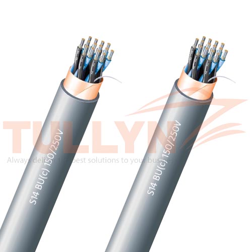
S14 BU(c) Unarmoured Fire Resistant Control Cable 150/250V
S14 BU(c) Unarmoured Fire Resistant Control Cable 150/250V Application
S14 BU(c) Unarmoured Fire Resistant Control Cable is used for Instrument circuit up to 250V, instrument safe systems or in fixed installation instrument, communication, control and alarm systems in both explosion risk and safe areas, general purposes with special non-fire-propagation properties and low emission of opaque smoke and toxic and corrosives gases, oil resistant.
All materials used to manufacture this cable are halogen-free. This design ensures that non-corrosive and low toxic gas in case of fire, and ensures this cable can be used for living, quarter and office areas. This S14 BU(c) cable can be installed on drilling ships, drilling platforms ( jack up, semi-submersible), Production Platforms ( TLP, semi-submersible, SPAR, fixed platforms) and FPSO/FSO.
S14 BU(c) Unarmoured Fire Resistant Control Cable 150/250V Standards
| Design | IEC60092-376, NEK TS 606:2009 |
| Conductor | IEC60228 |
| Insulation | IEC60092-351 |
| sheathed | IEC60092-359 |
| Flame Retardant | IEC 60332-1,IEC60332-3-22 |
| Fire Resistant | IEC 60331 |
| Smoke Density | IEC61034 |
S14 BU(c) Unarmoured Fire Resistant Control Cable 150/250V Construction
| Classification | Code | Construction details |
| Conductor | Tinned Annealed Stranded Copper Wire | |
| Insulation | B | Mica Tape+EP Rubber |
| Twinning | Colour coded cores twisted together | |
| Individual Shielding | (i) | Pairs/triples are layed up and collectively screened by copper backed polyester tape in contact with a stranded tinned copper drain wire. Pairs/triples are numbered with numbered tape or by numbers printed directly on the insulated conductors. |
| Outer Sheath | U | Halogen free thermosetting compound, SHF2, colored grey (blue for intrinsically safe). |
S14 BU(c) Unarmoured Fire Resistant Control Cable 150/250V Electrical Characteristic
| Nominal Cross Section Area | mm^2 | 0.75 | 1.0 | 1.5 |
| Nominal Conductor Diameter | mm | 1.1 | 1.3 | 1.6 |
| Maximum Resistant@20℃ | Ω/km | 26.3 | 19.3 | 12.9 |
| Mutual Capacitance | nF/km | 75 | 80 | 85 |
| Nominal Inductance@1KHz | MH/km | 0.727 | 0.686 | 0.667 |
| Maximum L/R@1KHz | μH/Ω | 20 | 25 | 35 |
| Operating Voltage | V | 250 | 250 | 250 |
S14 BU(c) Unarmoured Fire Resistant Control Cable 150/250V Specification
| No. of elements× No. of cores in element× Cross section |
Nominal Insulation Thickness |
Nominal Outer Sheath Thickness |
Nominal Overall Diameter |
Nominal Weight |
| (mm2) | mm | mm | mm | kg/km |
| 2×2×0.75 | 0.6 | 1.1 | 10.2 | 185 |
| 4×2×0.75 | 0.6 | 1.2 | 12.5 | 240 |
| 7×2×0.75 | 0.6 | 1.4 | 15.0 | 350 |
| 8×2×0.75 | 0.6 | 1.4 | 16.3 | 395 |
| 12×2×0.75 | 0.6 | 1.5 | 19.5 | 540 |
| 16×2×0.75 | 0.6 | 1.6 | 21.8 | 690 |
| 19×2×0.75 | 0.6 | 1.7 | 23.2 | 780 |
| 24×2×0.75 | 0.6 | 1.8 | 26.7 | 985 |
| 32×2×0.75 | 0.6 | 2.1 | 29.6 | 1225 |
| 2×3×0.75 | 0.6 | 1.2 | 12.0 | 205 |
| 3×3×0.75 | 0.6 | 1.2 | 13.1 | 265 |
| 4×3×0.75 | 0.6 | 1.3 | 14.4 | 320 |
| 7×3×0.75 | 0.6 | 1.3 | 17.4 | 475 |
| 8×3×0.75 | 0.6 | 1.5 | 19.5 | 590 |
| 12×3×0.75 | 0.6 | 1.6 | 22.9 | 745 |
| 16×3×0.75 | 0.6 | 1.7 | 25.6 | 965 |
| 19×3×0.75 | 0.6 | 1.8 | 27.2 | 1095 |
| 24×3×0.75 | 0.6 | 2.0 | 31.6 | 1405 |
| 2×2×1.0 | 0.6 | 1.1 | 10.7 | 210 |
| 4×2×1.0 | 0.6 | 1.1 | 13.3 | 285 |
| 7×2×1.0 | 0.6 | 1.4 | 16.0 | 415 |
| 8×2×1.0 | 0.6 | 1.4 | 17.3 | 465 |
| 12×2×1.0 | 0.6 | 1.6 | 20.8 | 645 |
| 16×2×1.0 | 0.6 | 1.7 | 23.3 | 825 |
| 19×2×1.0 | 0.6 | 1.8 | 24.7 | 940 |
| 24×2×1.0 | 0.6 | 1.9 | 28.8 | 1200 |
| 32×2×1.0 | 0.6 | 2.3 | 31.8 | 1495 |
| 3×3×1.0 | 0.6 | 1.2 | 14.0 | 310 |
| 4×3×1.0 | 0.6 | 1.4 | 15.3 | 380 |
| 7×3×1.0 | 0.6 | 1.6 | 18.6 | 570 |
| 12×3×1.0 | 0.6 | 1.6 | 24.4 | 900 |
| 16×3×1.0 | 0.6 | 1.7 | 27.3 | 1160 |
| 19×3×1.0 | 0.6 | 1.9 | 29.0 | 1325 |
| 24×3×1.0 | 0.6 | 2.1 | 33.7 | 1700 |
| 2×2×1.5 | 0.7 | 1.2 | 12.1 | 275 |
| 4×2×1.5 | 0.7 | 1.3 | 15.2 | 380 |
| 7×2×1.5 | 0.7 | 1.5 | 18.4 | 565 |
| 8×2×1.5 | 0.7 | 1.5 | 20.0 | 640 |
| 12×2×1.5 | 0.7 | 1.7 | 24.3 | 895 |
| 16×2×1.5 | 0.7 | 1.8 | 27.2 | 1150 |
| 19×2×1.5 | 0.7 | 1.9 | 28.6 | 1295 |
| 24×2×1.5 | 0.7 | 2.1 | 33.5 | 1670 |
| 32×2×1.5 | 0.7 | 2.3 | 37.0 | 2095 |
| 2×3×1.5 | 0.7 | 1.3 | 15.0 | 310 |
| 3×3×1.5 | 0.7 | 1.3 | 16.0 | 420 |
| 4×3×1.5 | 0.7 | 1.4 | 17.7 | 515 |
| 7×3×1.5 | 0.7 | 1.6 | 21.5 | 785 |
| 8×3×1.5 | 0.7 | 1.6 | 23.5 | 930 |
| 12×3×1.5 | 0.7 | 1.8 | 28.5 | 1255 |
| 16×3×1.5 | 0.7 | 1.9 | 31.9 | 1630 |
| 19×3×1.5 | 0.7 | 2.0 | 33.8 | 1855 |
| 24×3×1.5 | 0.7 | 2.2 | 39.3 | 2375 |
Please note that the above specifications are “general specifications” that pertain to the majority of our production. These specifications should only be used for general, informational purposes. All dimensions and specifications are nominal and are subject to normal manufacturing tolerances. All specifications are subject to change without prior notice. All pictures shown are for illustration purposes only. Actual product may vary. Classification certification like CCS, DNV, BV, LR, NK, KR, RS shall be provided upon request.


Reviews
There are no reviews yet.