N2XRY XLPE/PVC/SWA/PVC Armored Power Cable 0.6/1KV
N2XRY XLPE/PVC/SWA/PVC Armored Power Cable 0.6/1KV Application and Description
N2XRY power and control cable is used for indoor, outdoor and underground installation in ducts and in the open where better mechanical protection is required, or for higher tensile stress during installation and operation. Suitable for comparatively high ambient temperature due to high maximum permissible conductor temperature.
N2XRY is intended for power distribution of industrial applications and switching systems, power stations, residential connections and street lighting, as well as control cables for transmitting control pulses and measurements. Wherever increased electrical and mechanical protection are required.
It is used for installation in the underground, in water, outdoors, in concrete and cable ducts. Respecting the permissible operating temperature at the conductor of +90 °C permits a higher current carrying capacity than PVC insulated power distribution cables. The concentric conductor (C) can be used as a PE or PEN-conductor or as a screen
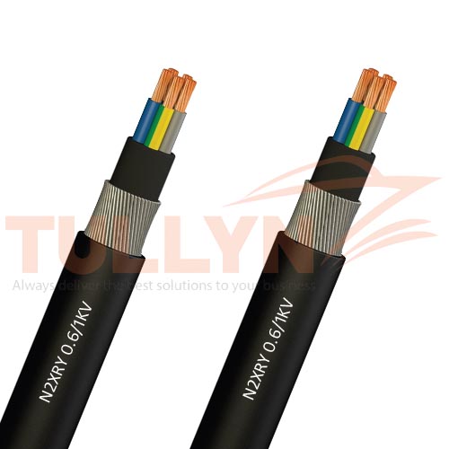
N2XRY XLPE/PVC/SWA/PVC Armored Power Cable 0.6/1KV Construction
| Conductor | – Solid or stranded, plain copper conductor – to DIN VDE 0295 cl. 1 or cl. 2, BS 6360 cl. 1 or cl. 2 and IEC 60228 cl. 1 or cl. 2 |
| Insulation | – Cross-linked polyethylene 2XI1 acc. to VDE 0276-604– Color-coded to DIN VDE 0293(HD 308) |
| Filler | – PVC filler |
| Armor | – Galvanized round steel / aluminum wire armour |
| Sheath | – PVC outer jacket DMV5 to HD 603.1 |
N2XRY XLPE/PVC/SWA/PVC Armored Power Cable 0.6/1KV Technical Characteristics
| Working voltage | 600/1000 volts |
| Test voltage | 3500 volts |
| Minimum bending radius | 15 x Ø |
| Flexing temperature | -5º C to +70º C |
| Fixed installation temperature | – 30º C to +70º C |
| Short circuit temperature | +250º C |
| Flame retardant | IEC 60332-1 |
| Insulation resistance | >20 MΩ x km |
N2XRY XLPE/PVC/SWA/PVC Armored Power Cable 0.6/1KV Specification
| Nominal crosssection | Overall diameter approx. | Net weight approx. | Conductor DC resistance at 20C max. |
| mm2 | mm | kg/km | ohm/km |
| 3×1.5 | 14.5 | 370 | 12.1 |
| 3×2.5 | 15.5 | 440 | 1.41 |
| 3×4 | 16.5 | 510 | 4.61 |
| 3×6 | 17.5 | 610 | 3.08 |
| 3×10 | 19.5 | 790 | 1.83 |
| 3×16 | 23 | 1100 | 1.15 |
| 4×1.5 | 15.5 | 410 | 12.1 |
| 4×2.5 | 16.5 | 490 | 7.41 |
| 4×4 | 17.5 | 590 | 4.61 |
| 4×6 | 18.5 | 710 | 3.08 |
| 4×10 | 21 | 930 | 1.83 |
| 4×16 | 24 | 1430 | 1.15 |
Other Specification will be available upon request.
Photographs are not to scale and do not represent detailed images of the respective products.
Note: All dimensions and specifications are nominal and are subject to normal manufacturing tolerances. All specifications are subject to change without prior notice. Photographs are not to scale and do not represent detailed images of the respective products. All pictures shown are for illustration purposes only. Actual product may vary. Other Specification will be available upon request.


Reviews
There are no reviews yet.