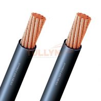
FR-MPYCY Shipboard Fire Resistant Control and Signal cables 150/250V
FR-MPYCY Shipboard Fire Resistant Control and Signal cables 150/250V Application
FR-MPYCY is intended for power circuit up to 250V, Lighting & Control circuit, also for fixed installation lighting & control in both explosion risk and safe areas, general purposes.
STANDARD APPLIED
Design guideline : JIS C 3410 (1999)
Material properties :
JIS C 3410 Insulation, EPR JIS C 3410 Sheath, PVC
Flame retardant :
IEC 60332-1
IEC 60332-3, Cat. A, ‘FA–’ type only
Fire Resistant
IEC 60331
– Any other cable marking can be applicable, when purchaser required
FR-MPYCY Shipboard Fire Resistant Control and Signal cables 150/250V Construction
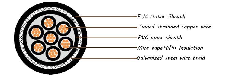
| Conductor | M | Tinned annealed stranded copper, class 2 according to IEC 60228 |
| Insulation | P | Mica tape+85°C EPR as per JIS C 3401 |
| Cabling | Insulated conductors shall be cabled. Flame retardant & non-hygroscopic fillers may be used |
|
| Bedding | Y | PVC as per JIS C 3401 |
| Armor | C | Galvanized steel wire braid |
| Sheath | Y | PVC as per JIS C 3401 |
| Core identification | Black No. on white insulation /Black No. on white insulation, G/Y | |
| Outer sheath color | Black |
FR-MPYCY Shipboard Fire Resistant Control and Signal cables 150/250V Technical Data
| Conductor cross-section | 1mm² |
| Conductor diameter | 1.3mm |
| Diameter over armour | 1.0mm |
| Average insulation thickness | 0.7mm |
| Rated Voltage Uo/U (Um) | 150 / 250 V |
| Max. DC resistance of the conductor at 20°C | 18.2Ohm/km |
| Test voltage | 1500V |
FR-MPYCY Shipboard Fire Resistant Control and Signal cables 150/250V Specification
250V FR-MPY;250V FR-MPYC;250V FR-MPYCY
| No.of cores | Conductor Size | Overall Diameter | Approx. Weight | ||||||||
| FR-MPY | FR-MPYC | FR-MPYCY | FR-MPY | FR-MPYC | FR-MPYCY | ||||||
| mm2 | Stranding | mm | ±mm | mm | ±mm | mm | ±mm | kg/km | |||
| 2 | 9.2 | ±0.5 | 10.4 | ±0.5 | 12.2 | ±0.5 | 95 | 170 | 225 | ||
| 4 | 10.4 | ±0.5 | 11.6 | ±0.5 | 13.4 | ±0.6 | 140 | 225 | 285 | ||
| 7 | 12.4 | ±0.6 | 13.6 | ±0.6 | 15.4 | ±0.6 | 210 | 320 | 385 | ||
| 12 | 16 | ±0.6 | 17.2 | ±0.6 | 19.2 | ±0.7 | 345 | 490 | 585 | ||
| 19 | 1 | 7/0.43 | 18.8 | ±0.7 | 20 | ±0.7 | 22.2 | ±0.8 | 510 | 680 | 790 |
| 27 | 22.6 | ±0.8 | 23.8 | ±0.8 | 26.2 | ±0.9 | 730 | 920 | 1080 | ||
| 37 | 25.3 | ±0.9 | 26.5 | ±0.9 | 29.1 | ±1.0 | 960 | 1180 | 1360 | ||
| 44 | 28.5 | ±1.0 | 29.7 | ±1.0 | 32.3 | ±1.1 | 1280 | 1420 | 1620 | ||
DISCLAIMER: Please note that the above specifications are “general specifications” that pertain to the majority of our production. Specifications and technical details should only be used for general, informational purposes only. For the actual specification, please check with us when order placed.


Reviews
There are no reviews yet.