P6 BFOU 3.6/6Kv Fire Resistant Cable
P6 BFOU 3.6/6Kv Fire Resistant Cable Application
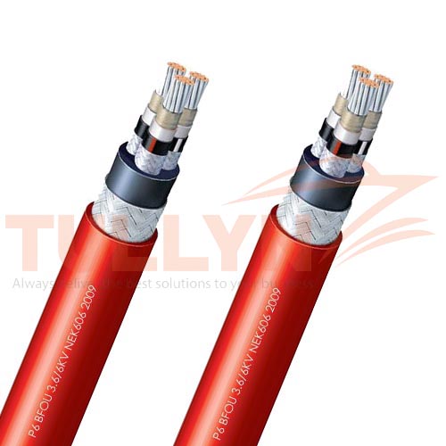
P6 BFOU 3.6/6Kv Fire Resistant Cable is fire resistant, flame retardant, low smoke, halogen free and mud resistant, used for fixed installation for medium voltage power.
These P6 BFOU 3.6/6Kv cables are intended for fixed installation for power and energy transmission with a rated voltage of 3.6/6KV. These cables can be installed on drilling ships, drilling platforms ( jack up, semi-submersible), Production Platforms ( TLP, semi-submersible, SPAR, fixed platforms) and FPSO/FSO.
P6 BFOU 3.6/6Kv Fire Resistant Cable Standards
| Design | IEC60092-354 |
| Conductor | IEC60228 |
| Insulation | IEC60092-351 |
| sheathed | IEC60092-359 |
| Flame Retardant | IEC 60332-1,IEC60332-3-22 |
| Fire Resistant | IEC 60331 |
| Smoke Density | IEC61034 |
P6 BFOU 3.6/6Kv Fire Resistant Cable Construction
| Classification | Code | Construction details |
| Conductor | Tinned Annealed Stranded Copper Wire | |
| Conductor Screen | Semiconducting material | |
| Insulation | B | Mica Tape+EP Rubber/XLPE |
| Insulation Screen | Semiconducting material and tinned copper wire braid | |
| Filler | Water blocking fillers, if required | |
| Bedding | Halogen free compound, PETP wrapping tape will be applied over the bedding, if required | |
| Inner Sheath | F | Halogen free thermosetting compound |
| Armor | O | Tinned Copper wire braided |
| Outer Sheath | U | Halogen-free Thermosetting compound SHF2 |
P6 BFOU 3.6/6Kv Fire Resistant Cable Electrical Characteristics
| Nominal Cross Section Area | mm² | 25 | 35 | 50 | 70 | 95 | 120 | 150 |
| Nominal Conductor Diameter | mm | 6.5 | 7.4 | 8.7 | 10.3 | 12.2 | 13.8 | 15.1 |
| Maximum DC Resistant@20℃ | Ω/km | 0.734 | 0.529 | 0.391 | 0.27 | 0.195 | 0.154 | 0.126 |
| Continuous Current Rating@45℃1 Core | A | 127 | 157 | 196 | 242 | 293 | 339 | 389 |
| Continuous Current Rating@45℃3 Core | A | 89 | 110 | 137 | 169 | 205 | 237 | 272 |
| Short Circuit Current 1s | A | 3580 | 5010 | 7150 | 10020 | 13590 | 17170 | 21460 |
| Operating Voltage | KV | 3.6/6 | 3.6/6 | 3.6/6 | 3.6/6 | 3.6/6 | 3.6/6 | 3.6/6 |
| Nominal Cross Section Area | mm² | 185 | 240 | 300 | 400 | 500 | 630 |
| Nominal Conductor Diameter | mm | 17.0 | 19.6 | 21.9 | 24.5 | 27.5 | 32.3 |
| Maximum DC Resistant@20℃ | Ω/km | 0.1 | 0.0762 | 0.0607 | 0.0475 | 0.0369 | 0.0286 |
| Continuous Current Rating@45℃1 Core | A | 444 | 522 | 601 | 690 | 780 | 890 |
| Continuous Current Rating@45℃3 Core | A | 311 | 365 | 421 | 483 | 546 | 623 |
| Short Circuit Current 1s | A | 26470 | 34340 | 42930 | 57230 | 71540 | 90140 |
| Operating Voltage | KV | 3.6/6 | 3.6/6 | 3.6/6 | 8.7/15 | 8.7/15 | 8.7/15 |
Note: For more than 4-cores, the current ratings may be calculated from the following formula (IN=I1/ ³√ N ), I1= Current rating for 1-core, N = Number of cores.
Ambient Temperature Correction Factors
| Ambient Temperature Correction Factors | 35 | 40 | 45 | 50 | 55 | 60 | 65 | 70 | 75 | 80 |
| Rating Factor | 1.1 | 1.05 | 1.0 | 0.94 | 0.88 | 0.82 | 0.74 | 0.67 | 0.58 | 0.47 |
P6 BFOU 3.6/6Kv Fire Resistant Cable Specification
| Construction No. of cores×Cross section |
Nominal Insulation Thickness |
Nominal Inner Sheath Thickness |
Nominal Outer Sheath Thickness |
Nominal Overall Diameter |
Nominal Weight |
| (mm²) | mm | mm | mm | mm | kg/km |
| 1×16 | 2.5 | 1 | 1.6 | 24.8 | 950 |
| 1×25 | 2.5 | 1 | 1.6 | 26.3 | 1110 |
| 1×35 | 2.5 | 1 | 1.7 | 27.6 | 1260 |
| 1×50 | 2.5 | 1 | 1.7 | 29.1 | 1460 |
| 1×70 | 2.5 | 1 | 1.8 | 30.9 | 1740 |
| 1×95 | 2.5 | 1 | 1.9 | 33.2 | 2110 |
| 1×120 | 2.5 | 1 | 1.9 | 34.9 | 2430 |
| 1×150 | 2.5 | 1.2 | 2 | 36.9 | 2890 |
| 1×185 | 2.5 | 1.2 | 2.1 | 39.1 | 3370 |
| 1×240 | 2.6 | 1.2 | 2.2 | 42.2 | 4100 |
| 1×300 | 2.8 | 1.2 | 2.3 | 44.7 | 4810 |
| 1×400 | 3 | 1.4 | 2.5 | 48.1 | 5810 |
| 1×500 | 3.2 | 1.4 | 2.6 | 52.1 | 7030 |
| 1×630 | 3.2 | 1.4 | 2.8 | 56.5 | 8630 |
| 3×16 | 2.5 | 1.2 | 2.3 | 48.2 | 3550 |
| 3×25 | 2.5 | 1.2 | 2.4 | 51.5 | 4180 |
| 3×35 | 2.5 | 1.4 | 2.5 | 54.7 | 4820 |
| 3×50 | 2.5 | 1.4 | 2.6 | 57.4 | 5490 |
| 3×70 | 2.5 | 1.4 | 2.8 | 61.6 | 6590 |
| 3×95 | 2.5 | 1.6 | 2.9 | 66.2 | 7920 |
| 3×120 | 2.5 | 1.6 | 3.1 | 70.1 | 9150 |
| 3×150 | 2.5 | 1.6 | 3.2 | 74 | 10460 |
| 3×185 | 2.5 | 1.6 | 3.4 | 78.6 | 12010 |
| 3×240 | 2.6 | 1.8 | 3.6 | 86.3 | 14690 |
| 3×300 | 2.8 | 1.8 | 3.9 | 92.3 | 17130 |
Please note that the above specifications are “general specifications” that pertain to the majority of our production. These specifications should only be used for general, informational purposes. All dimensions and specifications are nominal and are subject to normal manufacturing tolerances. All specifications are subject to change without prior notice. All pictures shown are for illustration purposes only. Actual product may vary. Classification certification like CCS, DNV, BV, LR, NK, KR, RS shall be provided upon request.


Reviews
There are no reviews yet.