Cement tank container
Cement tank container Introduction
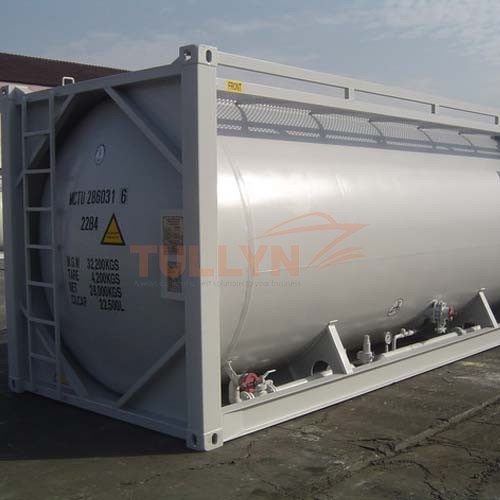
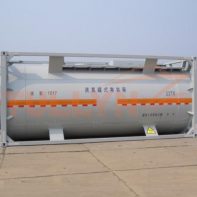
The cement tank container has an ISO 20ft tank container frame, usually has a bulk loading capacity of 22,500-litre. Our cement tank is separated for four purposes: tank containers for cement storage, short-sea, deep-sea shipping and rail transportation.
The tank containers are suitable for the transportation of bulk cement or coal powder by rail, road, and ship. All materials used in the construction shall withstand extremes of temperature range from -19ºC to +80ºC / -2,2ºF to +176ºF without effect on the strength of the container.
All tanks are of the highest quality design and construction and conform strictly to the latest international approvals.
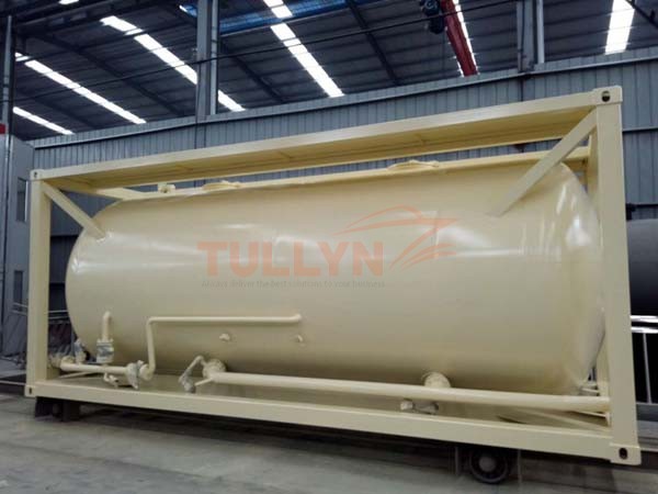
cement tank container
Cement tank container Specification:
| Frame Dimensions (L x W x H) | 6058 x 2438 x 2591 mm | |
| Nominal Capacity | 22700litre (±0.75%) | |
| Maximum Gross Mass | 30480 kgs | |
| Tare Mass | 4200 kg (± 3%) | |
| Design Temperature (Frame & Tank) | -20 to +70 °C | |
| Pressure | Working | 2.0 bar |
| Test | 2.6 bar | |
| Material | Tank (Shell & Ends) | Q345R |
| Frame | SPA-H or equivalent | |
| Pipe Work | Both right side and left side with two sets pipe system. One pipe system are consists of one inlet (for compress air), which diameter is 2″ and assembled with one 2″ ball valve, one 2″ check valve, one 2″ safety valve (only right side pipe system) and quick-open coupler, one outlet (for discharge cement), which diameter is 4″ and assembled with 4″ butterfly valve and quick-open coupler, one DN32 boosting ball valve connect the inlet and outlet together, one 2” relief line assembled with one 2” ball valve. |
|
| Manhole | 2 off 500mm quick release latch manlid. | |
| Air Inlet assembly |
DN 40 ball valve terminating with 1½” BSP connection and cap. The assembly is situated off centre on a tangential tank pad. |
|
| Top Discharge | DN80 stainless steel 316 tank pad with a blind flange. The assembly is fitted on centre on a horizontal tank pad. |
|
| Bottom Discharge |
DN80 45° Univalve Internal Footvalve part no. TBC fitted with an integrated butterfly valve terminating with a 3” BSP spigot with 3” BSP blind cap and chain. |
|
| Document holder |
A clear plastic document holder ø110mm is fitted to the rear right hand side beam. A drain hole is provided at the lowest point. |
|
| Calibration | A calibration plate marked in cm/litres is fitted on the spillbox side wall. No calibrated stainless steel grade dipstick and bracket fitted. |
|
| Design Code | ASME SECT. VIII, DIV. 1 where applicable. | |
| Approval | CCS | |
Please note that the above specifications are “general specifications” that pertain to the majority of our products. These specifications should only be used for general, informational purposes. The measurement/size of the goods delivered may be different from the data in the above table, please check with us when order placed.


Reviews
There are no reviews yet.